How to get your Petnet.io feeders somewhat working again.
UPDATE: While the method below works, it is no longer the best method to update your PetNet feeders… You use the same WiFi board but wiring it directly to the motor is the much better way now that PetNet has gone out of business…
Gen 1 Video is here: https://youtu.be/8SJ7n_RMAB8
Gen 2 Video is here: https://youtu.be/RO4WnxaW7CI
If you’re like me you have a Petnet.io pet-food dispenser for your pets and have loved it so far. However, a few weeks ago their services went offline. (I hear they may be closed permanently,) Which meant that our pets weren’t getting fed by the automatic schedule we setup. (And they never told us!) After a week or so I got to thinking I should be able to get some kind of workaround going for this thing, but I wanted the solution outside of the Petnet servers. I did a little digging on Amazon and found a solution for around $30. Even less if you have extra wire lying around, and less again if you can use a soldering iron.
….As a warning up front….
This will not restore complete functionality to your Petnet device!
This does not replace the Petnet.io software or hardware.
It cannot replace all functions.
Doing this will definitely Void any warranty.
It only enables remote pushing of the Front Button.
It can be setup on a loop timer or a schedule (limit of 7 events).
If the power goes out, this new WiFi capability is not on the Petnet internal battery.
I believe I have a Gen 1 feeder. I cannot guarantee these instructions will work on a Gen 2 or other device. The concept yes, the wiring no. If anyone wants to give me one to test out please contact me.
Also, feel free to hit up my Forum if you’d like to pass on any information regarding this post. https://www.allenscloud.com/forum/
THIS POST IS PROVIDED FOR INFORMATION PURPOSES ONLY. I ACCEPT NO RESPONSIBILITY FOR THE USE OF THIS INFORMATION. USE AT YOUR OWN RISK!
If none of that scares you off, please read on.
List of what you’re going to need is below at the affiliate links. If you know how to solder (and know what you’re doing) you only need the the WiFi Board. (If you don’t buy that one specifically, whatever you get must be 5V and have “inching” ability).
Affiliate Links:
WiFi Board: https://amzn.to/3g0377o

Wire connectors: https://amzn.to/2LFOYhz

18 Gauge wire: https://amzn.to/2Zc9ApP

OPTIONAL:
Wire Stripper: https://amzn.to/2WI8Uac

Step 1: Setup the new WiFi board first without connecting it to anything.
Download the app to your phone. Register for an account. Enter your WiFi network information. (It only works on 2.4 GHz, but it connected to my combined mesh, 2.4 and 5GHz with one name, network successfully.) Don’t follow the Pairing instructions that came with the device. Use the ones here: https://www.itead.cc/wiki/EWeLink_Introduction
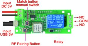
Only use the Input DC 5V OR the USB 5V, but never both! For initial setup you can use the Petnet devices power cord… Or find a different micro USB you have laying around.
Important Tip: the RF Pairing Button is not the one you want for WiFi pairing mode! (This other model of this board i found labels it the button that turns inching on and off manually…. something to test for the recommended model.) You should hold down the Match Button/manual switch for 10 seconds or until you see it start to blink fast. Now you’re in WiFi pairing mode. Then go to your phone settings and find the new network being broadcast that starts with ITEAD. Follow instructions at the link above. You may have to do this twice before it will complete. It will also most likely want to do a firmware update.
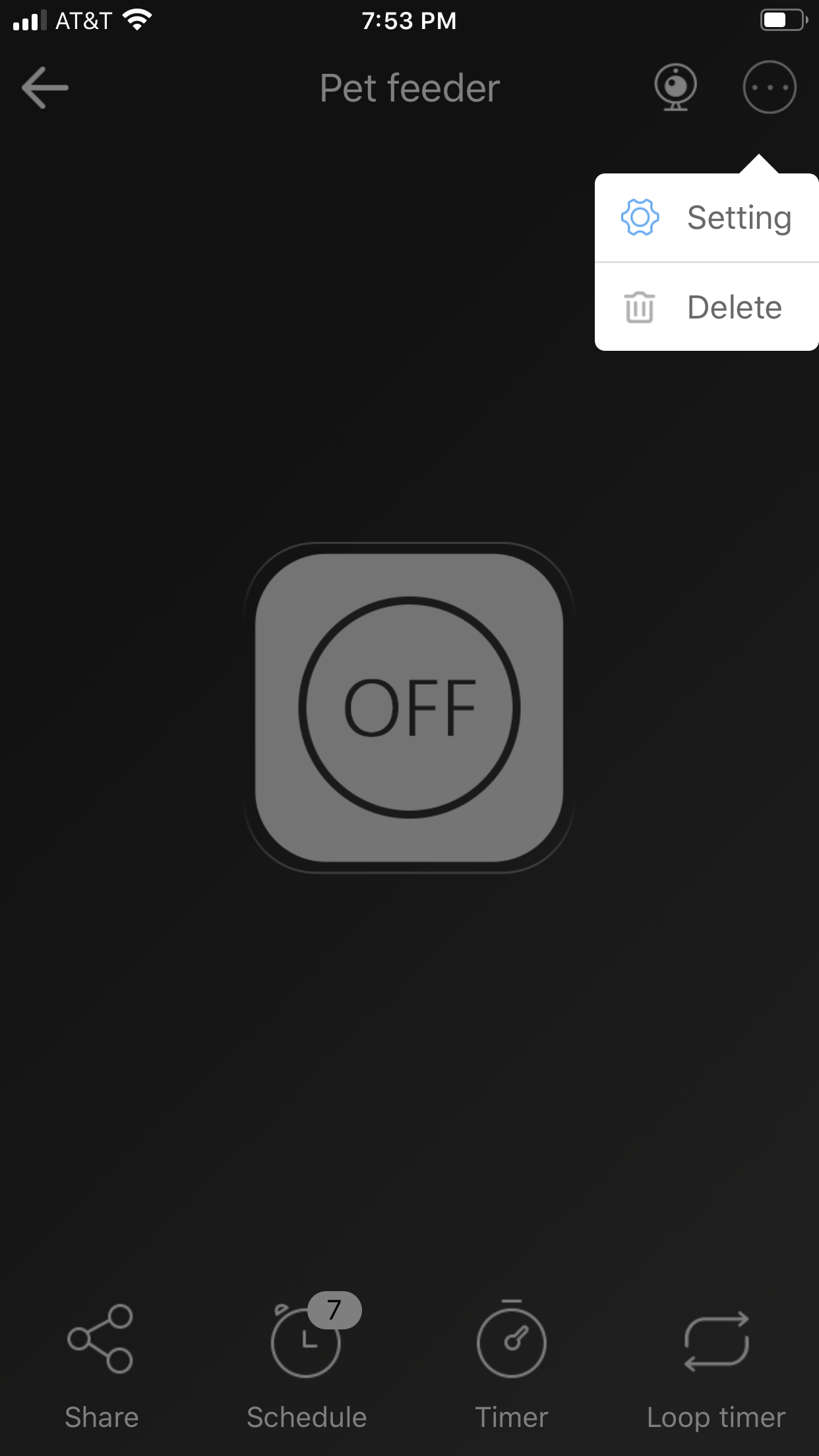
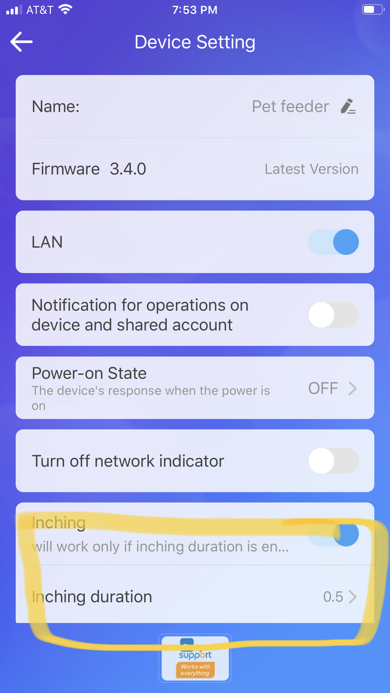
Important Tip 2: When you get the device setup, turn on “inching” and leave the default time setting in place. Test this feature to see the difference before and after, by using the On/Off switch in the App. You’ll hear the relay trip, and see the light on the board turn on and stay lit until you hit the Off switch in the app, then it will turn on then immediately off when you’ve turned on the “inching” mode. ( The inching feature simulates a button push, vs the default which is like flipping a light switch into the ON position. We don’t want to find out what will happen to the feeder if voltage is permanently applied to the button. )
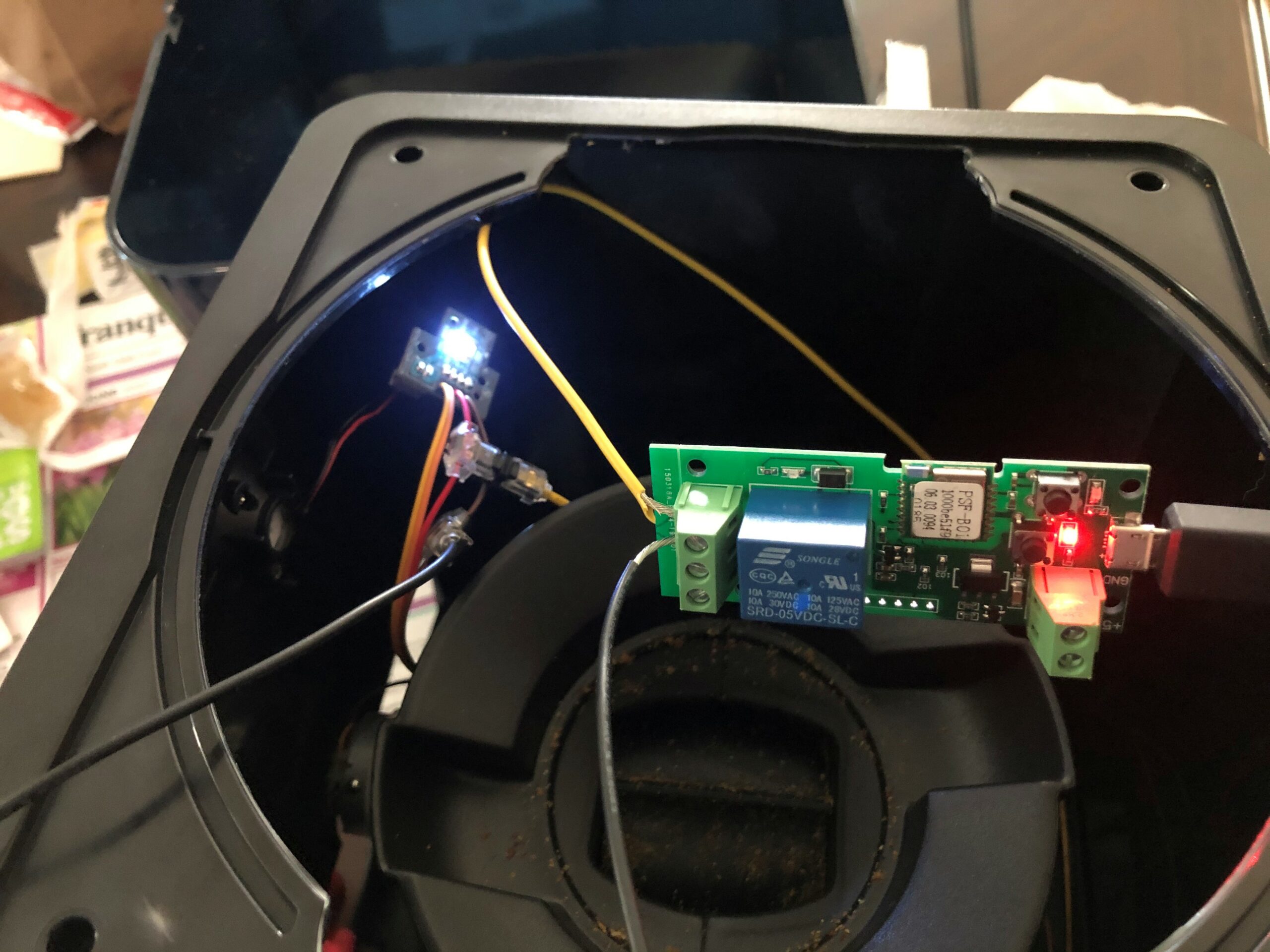
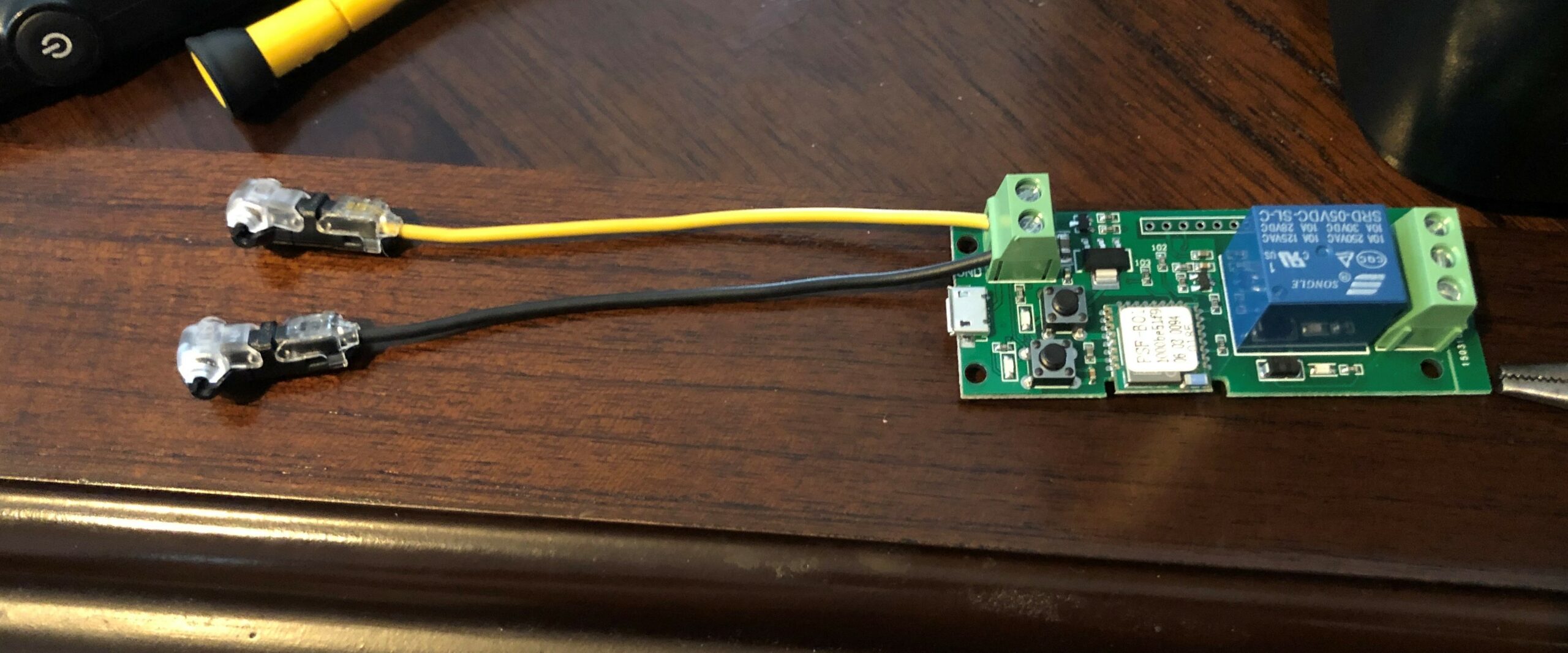
Picture shows test setup for Button Control Wires. But it is working.
Step 2: Open the Petnet feeder.
Unplug it.
Empty food from the tank. Twist the top tank to remove.
Remove food tray by pushing the button to eject it. (the food tray holds the battery and WiFi board that Petnet normally comes with. )
The bottom of the Petnet is only held in place by 4 notches. 2 on the left and 2 on the right if you’re facing the front. Use a screw driver to gently pop the sides out and the bottom will come out easily.
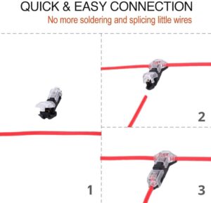
Step 3: Attach the wire clips to splice in the button control wires and the power wires.
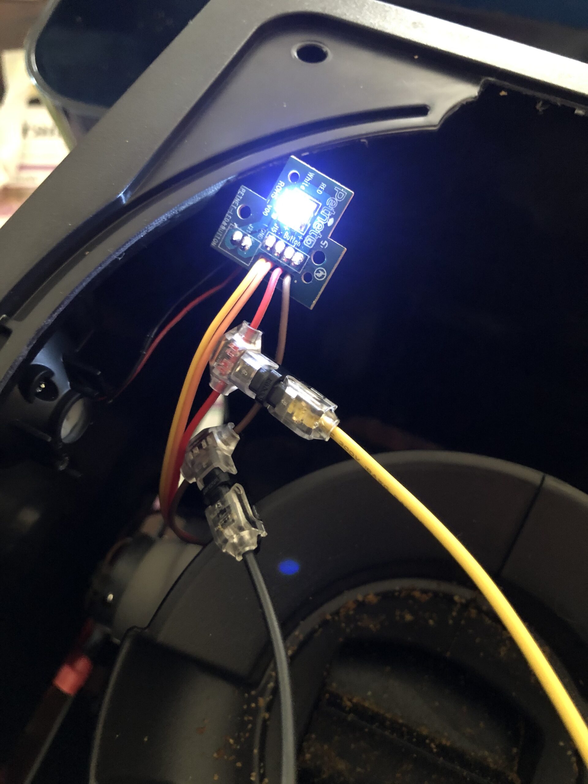
(Don’t attach the Button Control wires at this location like I did. It does work but you have to make the wires longer and take the entire device apart to get to it. Attach where my hand is in the Photo below after you separate the wires… )
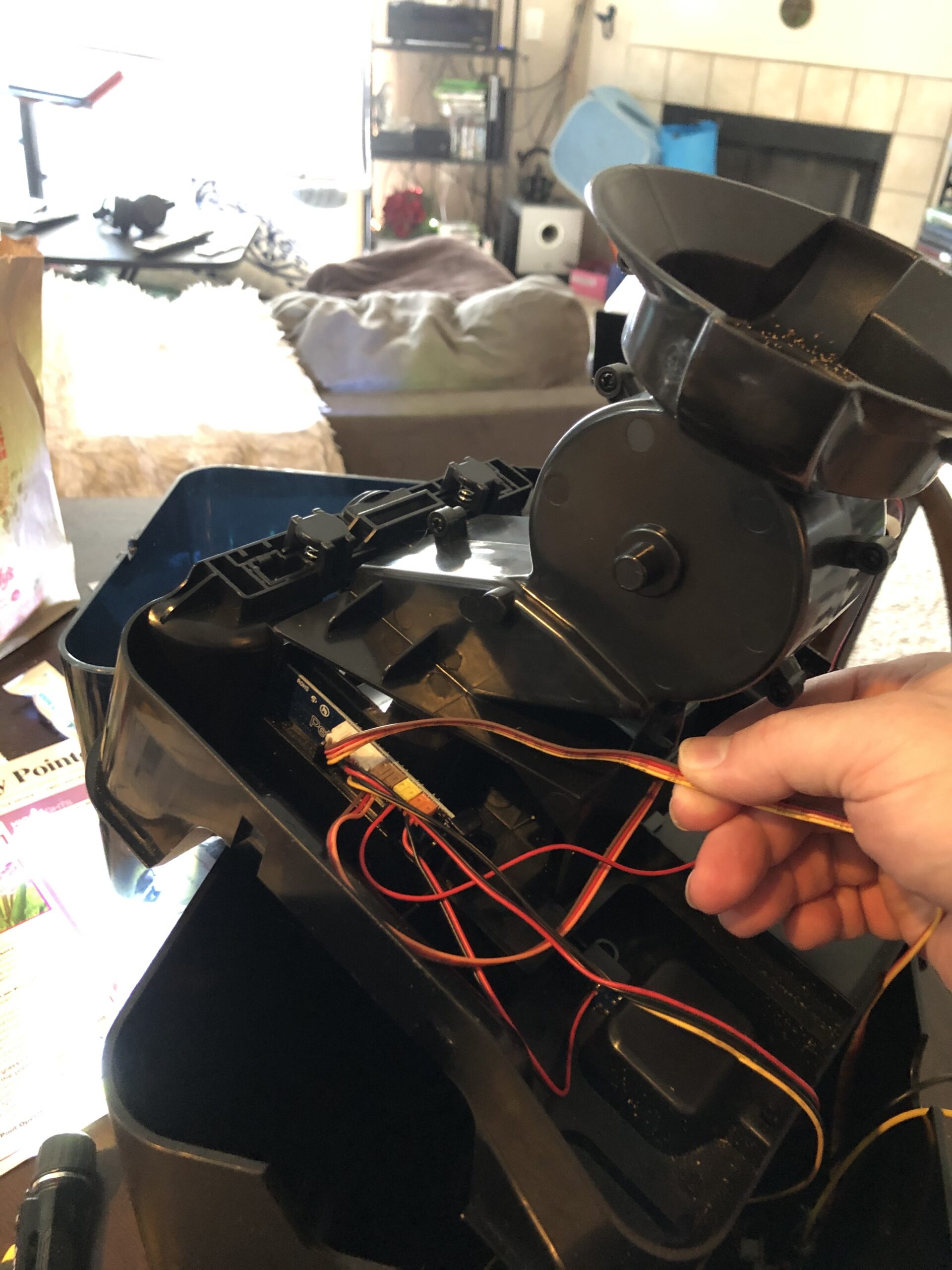
The cable in my hand goes from the control board to the button for manual feeding. This model has a Brown wire on the outside and a Red wire next to it. The Brown wire will go to the COM post on the WiFi Board. And the Red wire will go to the NO (Normally Open) post on the WiFi Board.

The wires are loosely bound together by thin plastic but they are separated near the main board. Gently pull the wires apart to roughly where my thumb is in the picture.
For power you have two options.
1. Drill a hole and run a Micro USB cord through to the board inside….
2. Tap the power coming in from the normal micro USB connector wires.
Option 2 is shown below.
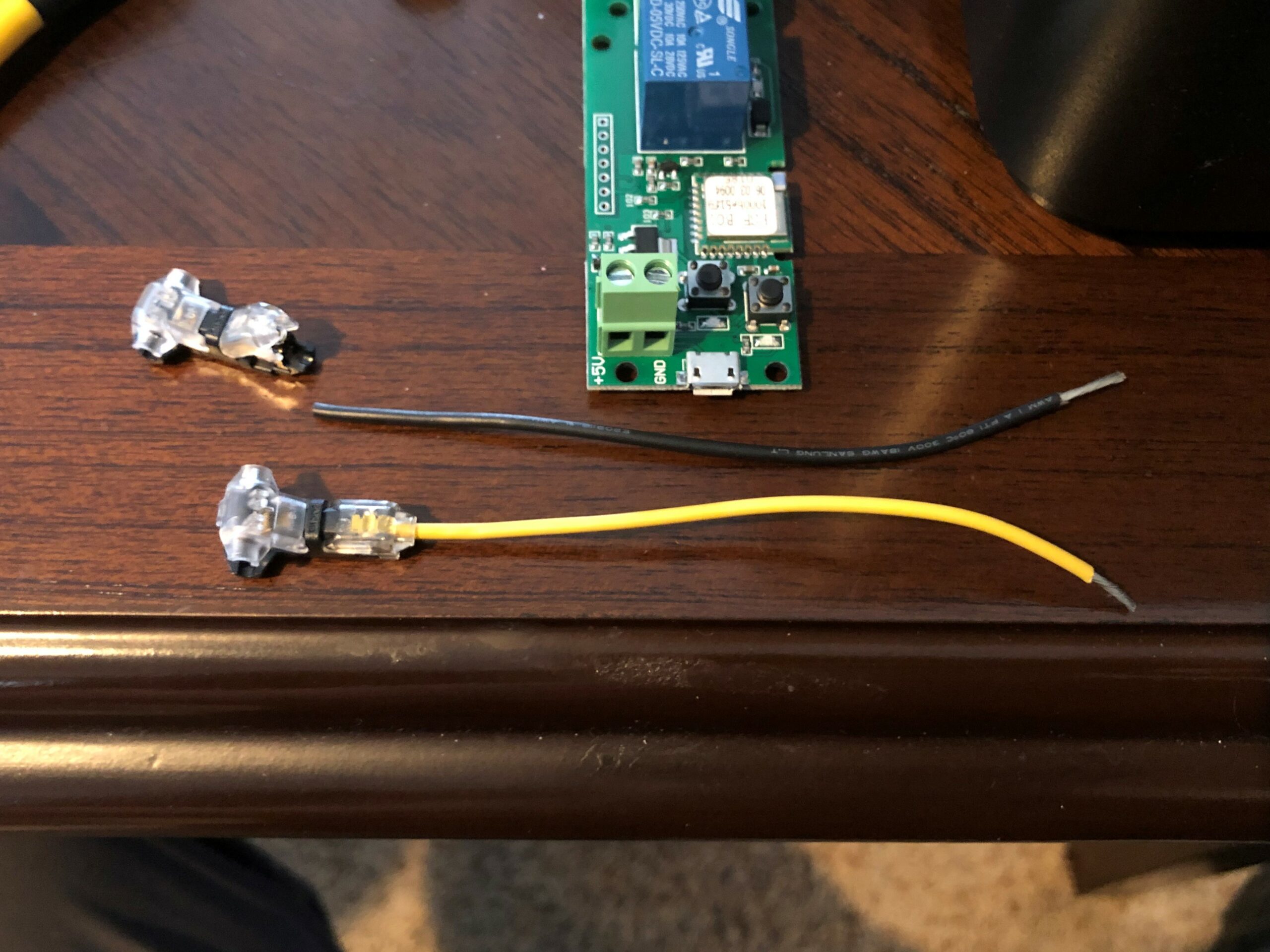
The end that goes into the clamp shouldn’t be stripped. The end that goes into the post on the WiFi board however must be stripped.
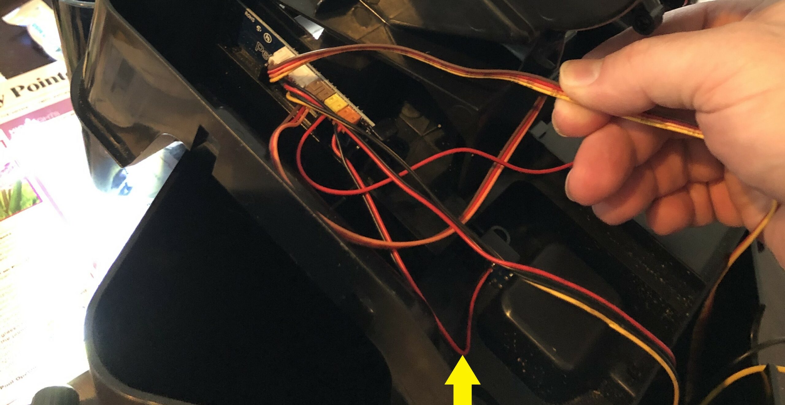
Separate the Red and Black cables that are indicated by the Yellow arrow in this photo. This power comes directly from the micro USB connector that normally powers the Petnet device. Attach the Black wire to Ground post (black wire in the photo above) and the Red to the +5V (Yellow wire in the photo above.) The wire connectors click together when done correctly. I used needle nose pliers. But don’t break the clips.
Step 4: Re-assemble the Petnet device and plug it in.
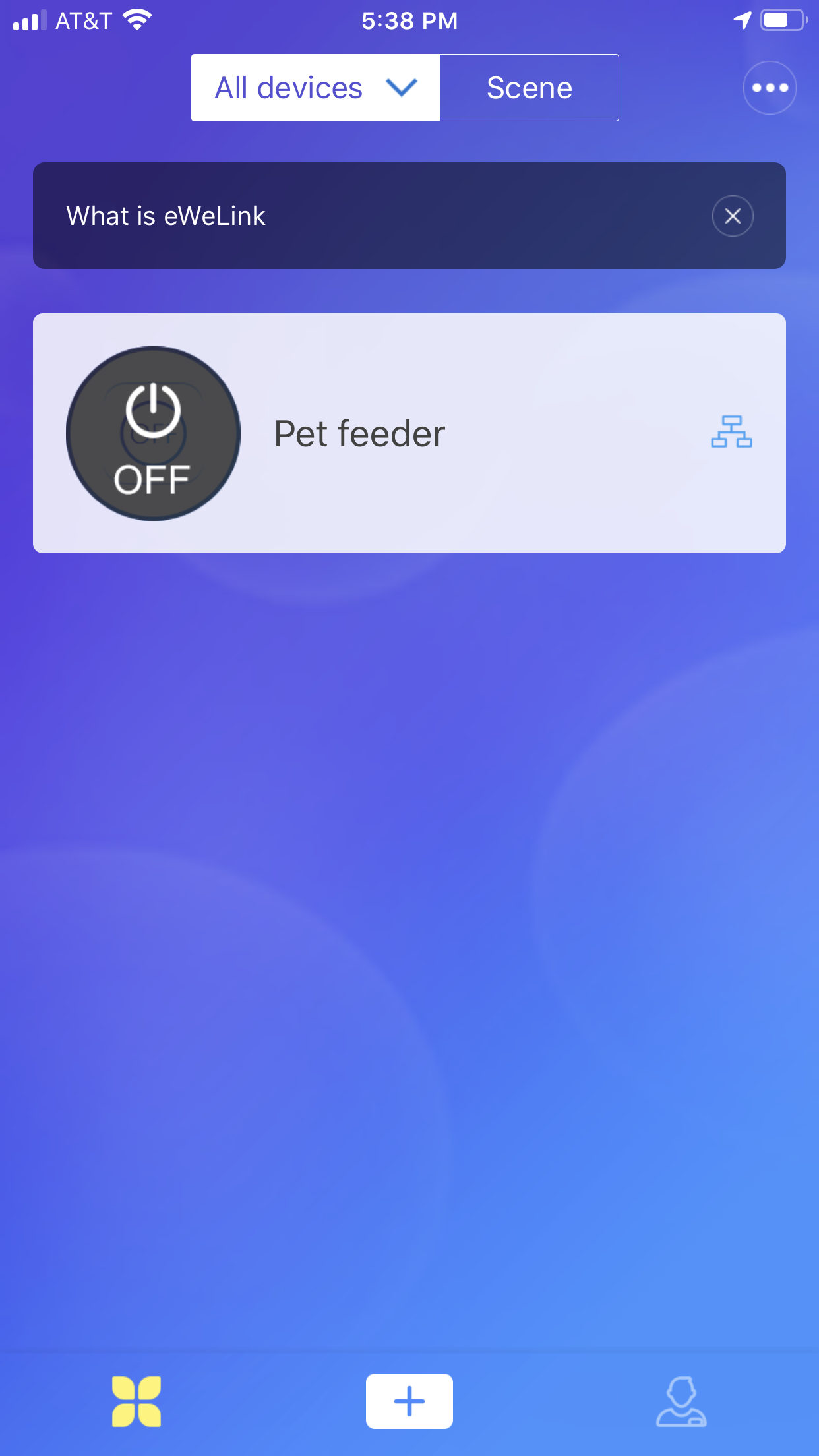
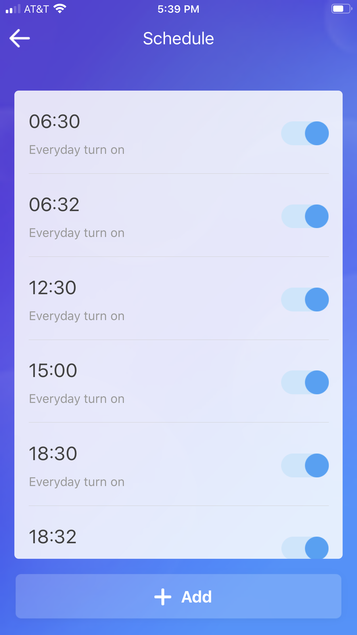
Step 5: Setup the Schedule or Loop timer to have the feeder dispense multiple times a day automatically. For the Loop timer I first set mine for a Cycle of every 6 hours with the Start action as ON. Then I enabled the “After” check below it and put 2 mins with the Action also as ON. I’ve done it this way because I think one button push is essentially a “snack”. So two pushes within 2 minutes should dispense enough for two cats and this will happen every 6 hours. I did switch to the Schedule but there is a limit of 7 events and ensuring the feeder goes off twice means two events a minute apart at certain times. I’m sure I’ll need to tweak the settings some. I may use a combination of the Schedule and the Loop to create three double feeds a day on the schedule and two snacks a day using the Loop… Please provide some feedback if there’s a better way to schedule feedings with the ewelink software or with some other home automation software that this device may be compatible with.
Thanks,
Allen
Looks great. I was thinking along the same line but with custom components. I’m at a bit of a disadvantage in that I don’t have a feeder – trying to fix my daughter’s remotely. Do you know the voltage across the feeder’s manual feed switch? I want to get the right relay.
I didn’t bother to test the voltage actually since it all works off a normal USB 5V input. The relay on the WiFi board I’m using is also 5V.
If you use home assistant, I believe the eWeLink is just a Sonoff device, so it has native integration!
Is there any way to regain the functionality to set meal sizes? We are ok with the schedule but the current setting is giving our cat too much food per serving
Yes, but only if you follow the method in the YouTube video for Gen 1 or Gen 2 feeders. This blog post I call Method 1, and it only lets you remotely hit the “snack” button. When using this new wifi board in the Videos, you are controlling the motor directly. So, when you setup the “inching” setting to say 2 seconds that’s how long the motor goes and spits out food. There’s only one downside to this. You only get to set one inching setting. So when you setup a schedule it feeds that same setting each time. I go with three smaller feeds per day. And if the bowl gets too full I go in and turn off the next feed schedule time. The petnet system with it’s sensors and software was definitely superior, but again this only gets you part of it back. And I think that’s better than throwing them away.
I did not bother to be subtle just used the wires from the motor straight to the board. I had extra wire but you could recycle wires in the petnet. So far so good. The other stuff is nice but harder to coordinate like the blocked motor sensor and the no feed sensor. Great hack!! I also drilled a hole for the cable
And that works too. There’s definitely “extra” wire in PetNet because of all the extra stuff not being used now. Glad it works out the way you want. 🙂
So you are saying VIDEO 1 is no longer the best method?
If we have Gen1 feeders, can you show us how to wire the wifi board directly to the motor?
BTW, youre the man!
No, no. I’m saying the Blog Post here which wires up just the front push button, is no longer the best method. It was just my first attempt. The 2 videos are the best way to do this as they wire the board to the motor directly… And thanks!
Why can’t I get this this to connect, I followed the instructions to the letter and it keeps gailing to connect to wifi.
That’s a tough one to answer because there are many different things it could be. The instructions leave a lot to be desired… I would try to reset the board (so that it is broadcasting it’s on WiFi signal again) and try the setup process again. Let me know what part of the process is breaking and maybe I can help. Of course it could also be a faulty board… but those seem to be rare.
any trick to get the app to link to the wifi controller?
Ohh yes… Use compatibility mode. I go over it in the Generation 2 video on YouTube… https://youtu.be/RO4WnxaW7CI
Hi. I’ve tried both quick pairing and compatibility mode and it won’t connect. The phone connects with no problem but the app just won’t recognize it.
Note: The EWeLink wiki linked is out of date. The images shown don’t match what I see on the android app.
Try looking at the Video on YouTube for the Gen2. I cover the app and pairing in that video.
I completed a modified install of the “hack”. I can use the wifi card and the front pushbutton. The battery remains functional for the local pushbutton as well. Method: I split the incoming USB power (parallel wiring) connecting USB ground in parallel with the motor black wire. Here is the key: I used 2 diodes on the 5v side. I added a diode to the red wire from motor connector toward motor. I created a node (junction) after the diode, one side to the motor the other side to a second diode coming off the relay NO of wifi board. I connected relay common to the USB positive. Both diodes point to motor and meet at node. Thus preventing any voltage/current in the reverse direction.
I am able to control the motor with the front button or the app. No problems. Works great.
Note: the relay only breaks the 5v to the motor. The ground is hardwired to the USB and the motor connector on the small petnet board.
Thanks for the idea with the wifi board and rewiring idea.
That sounds like a great modification! Glad it’s working for you the way you want. I’ve been certain there was a way to get some of the old parts working, I just knew it was beyond my skill set. Thanks for sharing…
Did you take any pics & parts list. This what i was thinking of doing.
Hi, I’m finally tired of pressing the button to feed and want to try the hack. If I’m going to dig into this thing I may as well go all out. Can you provide a list of parts and maybe a diagram of the addl. things to make the battery and manual feed button work with this wonder hack of Alan’s ??
Thanks to both of you guys!
Hi John. Did you happen to take a photo of your wiring? And on the diodes do you get 5v diodes? Any help would be appreciated . I tried to follow your extra hack info but can’t. (I’m a 62 year old cat lady, but I can solder!)
Thanks
Can you provide a simple drawing of your modification? I can send you my interpretation if you like. (I’ll need your email). Thanks.
Can I run two (2) petnet feeders off of one phone using one app? We had two feeders and I would like to have everything controlled from one phone if possible.
You can absolutely do that. In the video for the gen 2 you can see that at one point I have my current Gen 1 feeder setup and the Gen 2 I was testing with. The schedule for each (and the inching setting) are unique to the device though.
I was finally able to get my first WiFi board to pay to my wife’s IPhone after many tries, and I even named it. But it directly went offline. Can you provide any help, please?
Are you using a new power supply? Most issues are either loose wires or not using the right power supply….
I got everything working not long after my last post. I ended up using my old Android phone to run everything. Couldn’t seem to make things work with my wife’s I Phone. Did not appear to be a power supply issue. Everything is working! Thanks for your help.
Glad to hear it’s all working!
Thanks so much for this! Have been pushing the snack button on 2 feeders for months now. This totally did the trick! Really appreciate the effort and info on this.
Glad it helped!